
Joystick adapter for ZX Spectrum +2/+3
When I was fixing my ZX Spectrum +2B I could not test the joystick ports since I don’t own any Sinclair joysticks. To be able to use joysticks that use the Kempston (Atari compatible) standard I would have to make use of some sort of adapter to convert one into the other.
There is enough information available on both types of joysticks, so it is not hard to figure out how the pins need to be rewired (See table below). Since the Sinclair joysticks do not support auto-fire or additional fire-buttons only 6 pins (4 directions, 1 fire and ) need to be rewired.
| Joystick | ZX Spectrum | |
|---|---|---|
| Connector | Male | Female |
| Up | 1 | 5 |
| Down | 2 | 9 |
| Left | 3 | 7 |
| Right | 4 | 6 |
| Fire | 6 | 4 |
| GND | 8 | 8 |
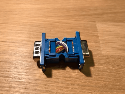
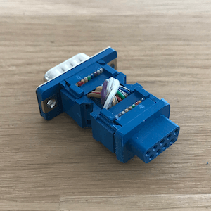
To be able to test the prototype adapter without any soldering (soldering these types of connectors is a pain…) I have ordered two solder-less DB9 connectors and with a couple of breadboard jumper wires I put together a little prototype.
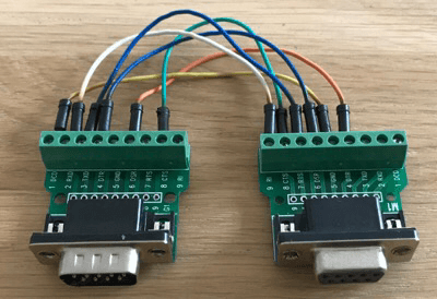 Prototype ZX Spectrum +2/+3 Joystick Adapter
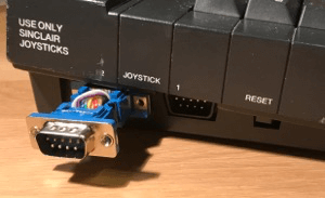
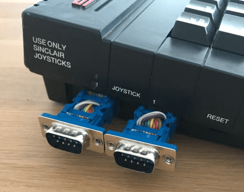
Due to the way the case design of the ZX Spectrum +2B I could only use it to test the second joystick port.
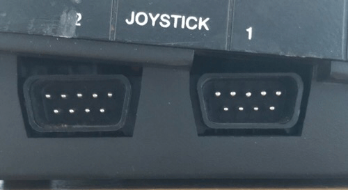 Joystick ports on the ZX Spectrum +2B
Testing the prototype
A Sinclair joystick works different from a Kempston joystick. Where a Kempston joystick can be read from I/O-port 31 (i.e. IN 31 in BASIC), the Sinclair joystick just emulates keyboard keys (0-9). This means there is no need for a little BASIC program, just fire up the ZX Spectrum +2B and jump into the +3 BASIC or 48K BASIC mode. The table below provides the expected values for both the first and the second joystick port.
| JS 1 | JS 2 | |
|---|---|---|
| Left | 6 | 1 |
| Right | 7 | 2 |
| Down | 8 | 3 |
| Up | 9 | 4 |
| Fire | 0 | 5 |
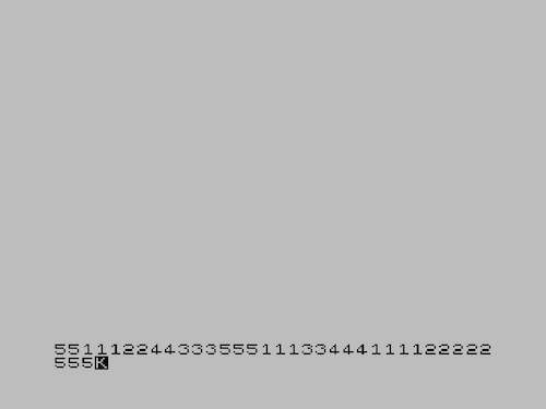 Screen output of testing the adapter (impressive )
So port 2 is working, lets make a more permanent adapter based on the prototype.
Final joystick adapter
To create a more permanent joystick adapter I selected the following materials (all these materials are available for cheap on sites like AliExpress)
| # | Description | Buy |
|---|---|---|
| 1 | DB9 Male crimp D-Sub connector | Buy |
| 1 | DB9 Female crimp D-Sub connector | Buy |
| 1 | (approx.) 10 cm flat ribbon cable | Buy |
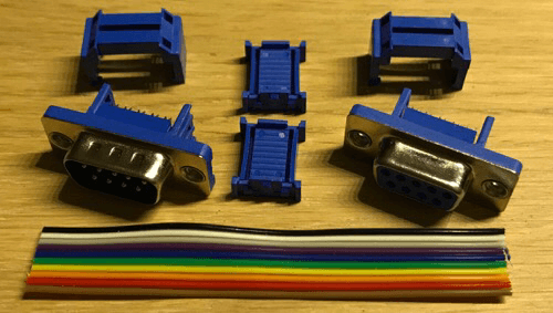 Materials used for the adapter
With this approach you only need some tape, wire cutters and a hammer of some groove joint pliers. For the ribbon cable I used a rainbow version, just to make it easier to identify each wire when making making the cross-links.
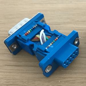
One thing to keep in mind when crossing the wires is the way the wires line up with the pins on the connectors
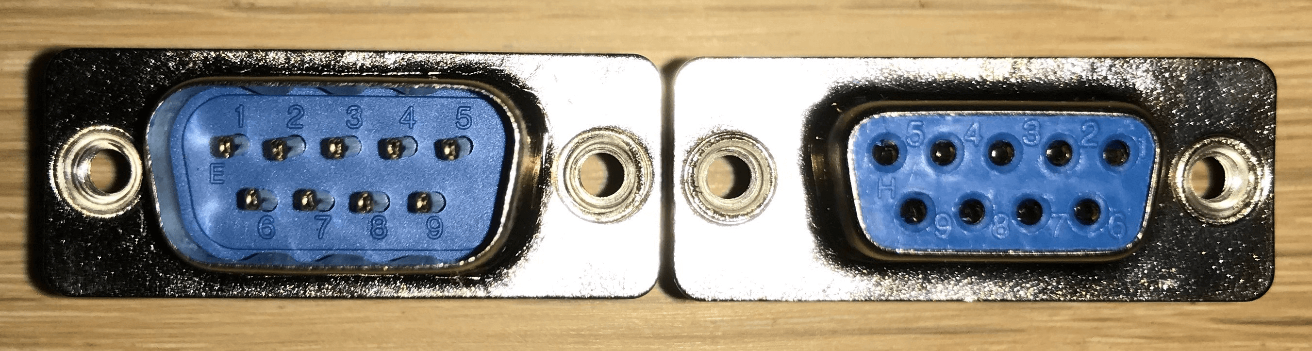 DB9 male and female pin numbering (click to zoom)
Although we only need six wires it is best to use all nine wires to make it easier to lineup the cable onto the clamps of the connector. Be very observant when putting the wires in the correct order, I have managed to botch 3 sets of connectors before getting it right…
Attach ribbon cable to the DB9 female connector and wires stripped down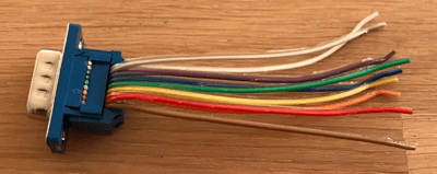 Ribbon cable connected
 Wires crossed
 Excess wire removed
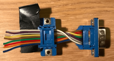
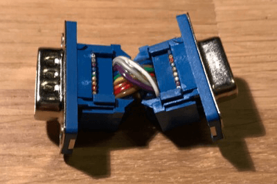
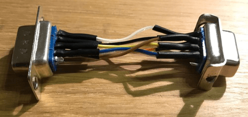
 Both sides glued together
This adapter is too wide to be used on Joystick port 1 on the ZX Spectrum +2B, for the ZX Spectrum +3 the adapter can be used in its current for on both joystick ports.
 Adapter connected to ZX Spectrum +2B
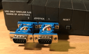 Adapters connected to ZX Spectrum +3
Since the female connector does not require the metal shielding it can be removed giving free access to the plastic tab allowing to be cut away. The male side of the connector does not need to be altered, also removing the shielding would make it vulnerable to be pins to be bent or even broken
 Shielding removed
 Plastic tabs removed
In hindsight it would have been easier to have done this as the first step of this little project.
Now two adapters can be connected to the ZX Spectrum +2B without any problems
 Two adapters connected to the ZX Spectrum +2B
Soldered version of the joystick adapter
Also made an adapter which does require soldering. Much to my surprise this version was quicker to make. You now really only need to solder the six wires and the process is easier since you can make each connection one at a time instead of doing them all at once. Additionally if you get a connection wrong you can de-solder the wire and try again.
Since I am not that proficient in soldering I added heat-shrink tubing around the connections to make sure there are no shorts on any of the connections. Also the tabs on the female connector have been bend backwards.
 Soldered connectors
I tried to put it all inside a regular DB9 case, but there is not enough room to put it all neatly inside. The holes for the bolts prevent it female connector from fitting (also had to remove the metal shielding from the connector). Had to resort to hot-glue to fixate the female connector in-place.
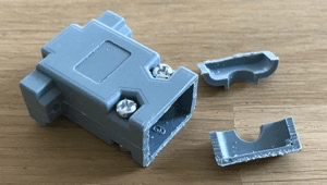 Cut of end of the DB9 case
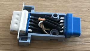 Connectors inside the case
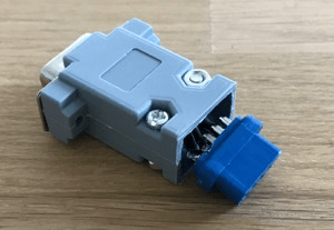 Closed casing
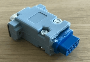 ‘Finished’ product
Now that is ‘finished’ I must say it looked a lot better in my mind. also the case is to bulky, so this version can only be used on a ZX Spectrum +3.