
Fixing some ZX Spectrum Joystick Interfaces
On eBay I bought a set of four untested (which usually means broken) joystick interfaces for the ZX Spectrum, based on the pictures provided they all looked fine. Although one seemed to be missing the keyway peg at pin 3.
The set consisted of the following interfaces
- 2 x Spectrum Joystick Interface MK2 by RAM Electronics Ltd
- 1 x Cheetah Spectrum Joystick Interface
- 1 x Unknown brand
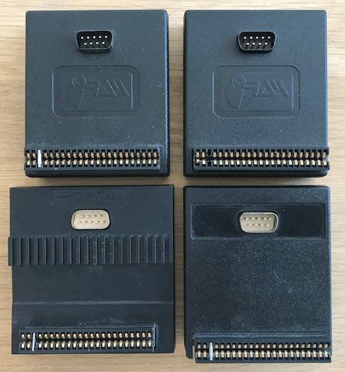 Set of ZX Spectrum Joystick Interfaces
Upon arrival the one missing the keyway also had a broken casing around the edge connector and a little piece on the side of the edge connector is missing. The broken plastic could be easily ‘repaired’ with a little bit of super glue. The missing part is, well missing, but the interface can work just fine without it.
BASIC Program
To quickly test the interfaces I wrote the following tiny BASIC program
10 LET X=IN 31
20 PRINT AT 0,0;"Status = ";X;"  "
30 GOTO 10
The following table lists the expected values for each direction/action. Up+Left would give a value of 10 (8 + 2) and combined with Fire it would return 26.
| Action | Status |
|---|---|
| Center | 0 |
| Right | 1 |
| Left | 2 |
| Down | 4 |
| Up | 8 |
| Fire | 16 |
Testing the joystick interfaces
As could be expected from the title of the article not all of the interfaces are in working order
Two of the interfaces were working perfectly (one of the RAM interfaces and the one of the unknown brand). The Cheetah and the other RAM interface did not fully work.
For the Cheetah interface the test program shows that everything is working, except for the down position.
Before testing the RAM interface I cut a little piece of plastic (roughly 6,5 mm x 4,5 mm x 1,4 mm) to create a keyway peg. With the new keyway peg in place I at least know that all of the connectors are lining up and I won’t cause additional damage to either the RAM interface or even worse my ZX Spectrum 48K used for testing.
 Keyway peg half inserted
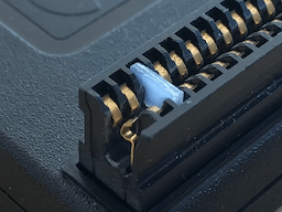 Keyway peg completely inserted
With the RAM interface only the Center position (0) and Fire button (16) work as expected, but any of the directions also seem to trigger the fire button (the value jumps between the expected value and the value+16).
Fixing the Cheetah Joystick Interface
The PCB of the Cheetah interface looks to be suffering from dry solder connections, the DB9 connector can be wiggled around. After applying some fresh solder to the DB9 connections it appeared that one of the solder pads had completely come lose from the PCB itself.
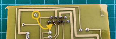 Broken off solder pad
The following image is the DB9 connector as seen from console side of the joystick (front-side), meaning we have to lift the image horizontally to easily map it to what we have on the PCB.
 DB9 Connector layout
Combined with the information of the mapping table of the pins it matches the issue I see exactly, the pin missing the solder pad is the one related to the Down position of the joystick.
| Pin | Description |
|---|---|
| 1 | Up |
| 2 | Down |
| 3 | Left |
| 4 | Right |
| 5 | Paddle B, not connected |
| 6 | Trigger/Fire |
| 7 | +5V |
| 8 | Ground |
| 9 | Paddle A, not connected |
To resolve this just I soldered a wire between the pin and the nearest connection point (based on the PCB lanes). Some of the other connections will need to be re-soldered. Not the best soldering job, I admit, but it gets the job done. I will have to practice soldering some more to get better results in the future.
 Fixed Cheetah Joystick Interface
Fixing the RAM Joystick Interface
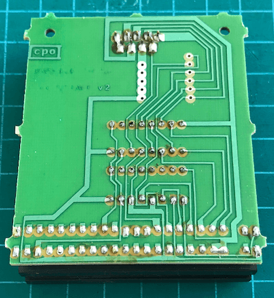
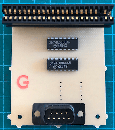
The PCB for the RAM interface looks fine. Initially I though the upper-left two pins might be an issue but these pins (5 and 8) have no function on the ZX Spectrum.
 PCB of the RAM Joystick Interface
I performed a continuity-test on the PCB and this also gave no clue on what the problem might be with this joystick interface (other than the fact this piece of hardware is about 35 years old).
Several of the solder connections were looking dull and just to be sure I removed all of the old connections and redid them all. Testing the interface after this change sadly enough gave the same results. It still auto-fires in when moving the stick in any of the directions.
On the PCB are also two chips (SN74LS366AN) and just to be sure I re-soldered all of the pins for the both of them. It seemed to make it a little better, but still not good enough.
 PCB front-side of the RAM Joystick Interface
A quick Google-search provided me with a data sheet of this package, although from Texas Instruments (the working RAM joystick interface is using this version) instead of Motorola. These chips are Hex bus drives with 3-state outputs. Hmmm, okay…
Maybe one or both of these IC’s are broken, but at this moment I have no clue how to test this assumption or even if these are the source of the problem. I was able to find a compatible type of chip on AliExpress, so I ordered some.
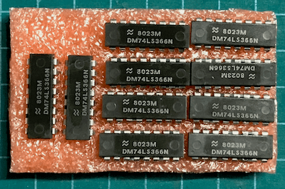 New set of SN74LS366AN chips
Instead of soldering the chips directly onto the PCB I installed two DIP sockets, making it easier test and/or replace chips if necessary.
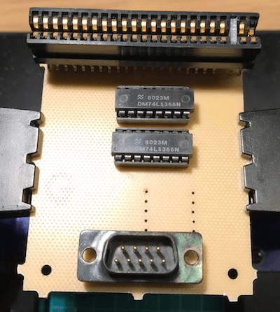 Sockets and chips installed
After installing the new chips the interface was working properly agian .
Identifying the unknown brand Joystick Interface
The outside of the joystick interface has no identifying information either embossed or printed, so we need to take a look at what is inside it.
After opening the case of the joystick interface I noticed that the PCB looks identical to the one from RAM (including the G on the front and cpo on the back), also the same chips are being used. So either it is a RAM interface with a different case or maybe a knock-off.