
Building a micro-controller programmer
In preparation of assembling a TZXDuino (compact) I need to be able to program an Atmel ATmega328P micro-controller.
I have a bunch of Raspberry Pi’3 lying around doing nothing and it would be nice to be able to use one of these Raspberry Pi’s as a programmer unit. After some research there are plenty of tutorials available on how to program an ATmega328P micro-controller (and a couple of other micro-controllers) using a Raspberry Pi.
All of the tutorials require you to use a breadboard and a couple wires, resistors, oscillator and some capacitors. For micro-controllers like the ATtiny45 and ATtiny85 wires and resistors is enough.
Putting together the breadboard AVR programmer
I put together a schematic in Autodesk EAGLE using the information found on the Internet
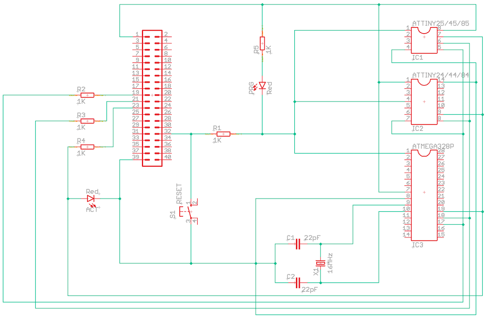 AVR programmer schematic
from which I made a breadboard version of the AVR programmer circuit (excluding the parts for the ATtiny micro-controllers). The reset switch is now just simply a wire connected to pin 1 of the ATmega328p, which can be connected to ground to reset the micro-controller.
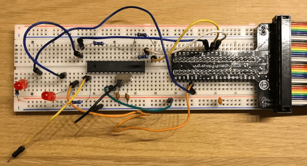 AVR Programmer breadboard for the ATmega328P micro-controller
Setting up the Raspberry Pi
First step is to prepare the Raspberry Pi. I usually perform the following steps to setup a new Raspberry Pi
- Create Raspbian SD card using the latest available image from official download page
- Create a file named
wpa_supplicant.confto setup WiFi connectivity or you can use the Ethernet-port. For more info see my post on building a mining stack of Pi’s - Create a file named
sshto enable ssh by default - Fix locale setting (set to en_US.UTF-8)
- Update the OS and installed packages (
sudo apt-get update/upgrade) - Reboot
- Install
gitandscreen(just in case) - Change Raspberry Pi configuration (
sudo raspi-config)- Change hostname (I named mine
avrprogrammer) - Change password for the
pi-account - Set correct timezone (For this would be Europe/Amsterdam)
- Activate SPI and I2C (not sure if this is really necessary, but doesn’t hurt either)
- Change hostname (I named mine
- Final reboot (you will be prompted when exiting
raspi-condfig)
next step is to install avrdude. Execute the command sudo apt-get install avrdude to install the latest version of avrdude onto the Raspberry Pi. When installation has completed edit the configuration file of avrdude using the command sudo nano /etc/avrdude.conf. Search for linuxgpio and uncomment the lines listed below and provide the GPIO-pins to be used when uploading code to the micro-controller
programmer
  id    = "linuxgpio";
  desc  = "Use the Linux sysfs interface to bitbang GPIO lines";
  type  = "linuxgpio";
  reset = 12;
  sck   = 11;
  mosi  = 10;
  miso  = 9;
;
Test the setup using the command sudo /usr/bin/avrdude -p m328p -c linuxgpio -v -t, where m328p informs avrdude that it will be addressing an ATmega328p.
pi@avrprogrammer:~ $ sudo /usr/bin/avrdude -p m328p -c linuxgpio -v -t

avrdude: Version 6.3-20171130
         Copyright (c) 2000-2005 Brian Dean, http://www.bdmicro.com/
         Copyright (c) 2007-2014 Joerg Wunsch

         System wide configuration file is "/etc/avrdude.conf"
         User configuration file is "/root/.avrduderc"
         User configuration file does not exist or is not a regular file, skipping

         Using Port                    : unknown
         Using Programmer              : linuxgpio
         AVR Part                      : ATmega328P
         Chip Erase delay              : 9000 us
         PAGEL                         : PD7
         BS2                           : PC2
         RESET disposition             : dedicated
         RETRY pulse                   : SCK
         serial program mode           : yes
         parallel program mode         : yes
         Timeout                       : 200
         StabDelay                     : 100
         CmdexeDelay                   : 25
         SyncLoops                     : 32
         ByteDelay                     : 0
         PollIndex                     : 3
         PollValue                     : 0x53
         Memory Detail                 :

                                  Block Poll               Page                       Polled
           Memory Type Mode Delay Size  Indx Paged  Size   Size #Pages MinW  MaxW   ReadBack
           ----------- ---- ----- ----- ---- ------ ------ ---- ------ ----- ----- ---------
           eeprom        65    20     4    0 no       1024    4      0  3600  3600 0xff 0xff
           flash         65     6   128    0 yes     32768  128    256  4500  4500 0xff 0xff
           lfuse          0     0     0    0 no          1    0      0  4500  4500 0x00 0x00
           hfuse          0     0     0    0 no          1    0      0  4500  4500 0x00 0x00
           efuse          0     0     0    0 no          1    0      0  4500  4500 0x00 0x00
           lock           0     0     0    0 no          1    0      0  4500  4500 0x00 0x00
           calibration    0     0     0    0 no          1    0      0     0     0 0x00 0x00
           signature      0     0     0    0 no          3    0      0     0     0 0x00 0x00

         Programmer Type : linuxgpio
         Description     : Use the Linux sysfs interface to bitbang GPIO lines
         Pin assignment  : /sys/class/gpio/gpio{n}
           RESET   =  12
           SCK     =  11
           MOSI    =  10
           MISO    =  9

avrdude: AVR device initialized and ready to accept instructions

Reading | ################################################## | 100% 0.00s

avrdude: Device signature = 0x1e950f (probably m328p)
avrdude: safemode: lfuse reads as FF
avrdude: safemode: hfuse reads as DA
avrdude: safemode: efuse reads as FD
avrdude>
So it appears everything is hooked up correctly. Entering quit will exit avrdude.
To get a list of all of the supported micro-controllers use the command avrdude -c avrisp. The list is quite extensive.
Since we hooked up an external oscillator (16Mhz) to the ATmega328p we need to make some changes to the fuses by running the following command sudo /usr/bin/avrdude -p m328p -c linuxgpio -U lfuse:w:0xdf:m -U hfuse:w:0xdf:m -U efuse:w:0xf9:m -U lock:w:0xff:m
avrdude: safemode: lfuse changed! Was df, and is now ff
Would you like this fuse to be changed back? [y/n]
avrdude: safemode: hfuse changed! Was df, and is now ff
Would you like this fuse to be changed back? [y/n]
avrdude: safemode: efuse changed! Was f9, and is now ff
Would you like this fuse to be changed back? [y/n]
avrdude: safemode: Fuses OK (E:F9, H:DF, L:DF)

avrdude done.  Thank you.
and to check to see if it worked run the command sudo /usr/bin/avrdude -p m328p -c linuxgpio -v
avrdude: AVR device initialized and ready to accept instructions

Reading | ################################################## | 100% 0.00s

avrdude: Device signature = 0x1e950f (probably m328p)
avrdude: safemode: lfuse reads as DF
avrdude: safemode: hfuse reads as DF
avrdude: safemode: efuse reads as F9

avrdude: safemode: lfuse reads as DF
avrdude: safemode: hfuse reads as DF
avrdude: safemode: efuse reads as F9
avrdude: safemode: Fuses OK (E:F9, H:DF, L:DF)

avrdude done.  Thank you.
So it seems to be correctly applied. Whenever a new ATmega328p is inserted into the breadboard the fuses will have to be set again.
On the page ‘AVR Fuse Calculator for ATmega328P’ you can see which options are enabled/disabled by applying the above fuse-values. The article ‘How to set the AVR Fusebits’ provides further information on the topic on setting fusebits.
Uploading code to the ATmega328p
To create/compile code for the micro-controller I opted to also install the Arduino IDE onto the Raspberry Pi. First I installed in using the command sudo apt-get install arduino (this installation takes a while to complete), but this does not give you the latest Arduino IDE as is available from the official Arduino site.
wget http://downloads.arduino.cc/arduino-1.8.8-linuxarm.tar.xz
tar -xf arduino-1.8.8-linuxarm.tar.xz
sudo mv arduino-1.8.8 /opt
/opt/arduino-1.8.8/install.sh
Up till now all was done from the command-line (via ssh), but Arduino requires a graphical user interface. Starting the Arduino IDE from the Unix shell just gets you the following result
pi@avrprogrammer:~ $ arduino
Exception in thread "main" java.lang.ExceptionInInitializerError
    at processing.app.Preferences.save(Preferences.java:735)
    at processing.app.Preferences.init(Preferences.java:249)
    at processing.app.Base.main(Base.java:117)
Caused by: java.awt.HeadlessException:
No X11 DISPLAY variable was set, but this program performed an operation which requires it.
    at sun.awt.HeadlessToolkit.getMenuShortcutKeyMask(HeadlessToolkit.java:236)
    at processing.core.PApplet.<clinit>(Unknown Source)
    ... 3 more
After closing the ssh session I started a new ssh session with one additional parameter -Y which enabled X11 forwarding (via XQuartz which is bundled with MacOS). Within this new session starting Arduino with the command /opt/arduino-1.8.8/arduino will (eventually) display the Arduino IDE and we can open the obligatory Blink sketch and compile it .
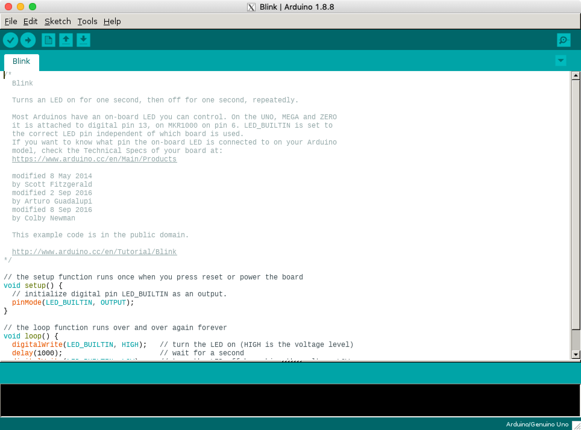 Arduino IDE via X11 forwarding
With the ‘Export compiled Binary’-option under ‘Sketch’ we can export the .hex version of the compiled code to the same folder as the sketch itself. There will be two .hex-files but we are only interested in the one with ‘standard’ within the name of the file. Filenames (and the number of files) differ based on the board selected within the Arduino IDE.
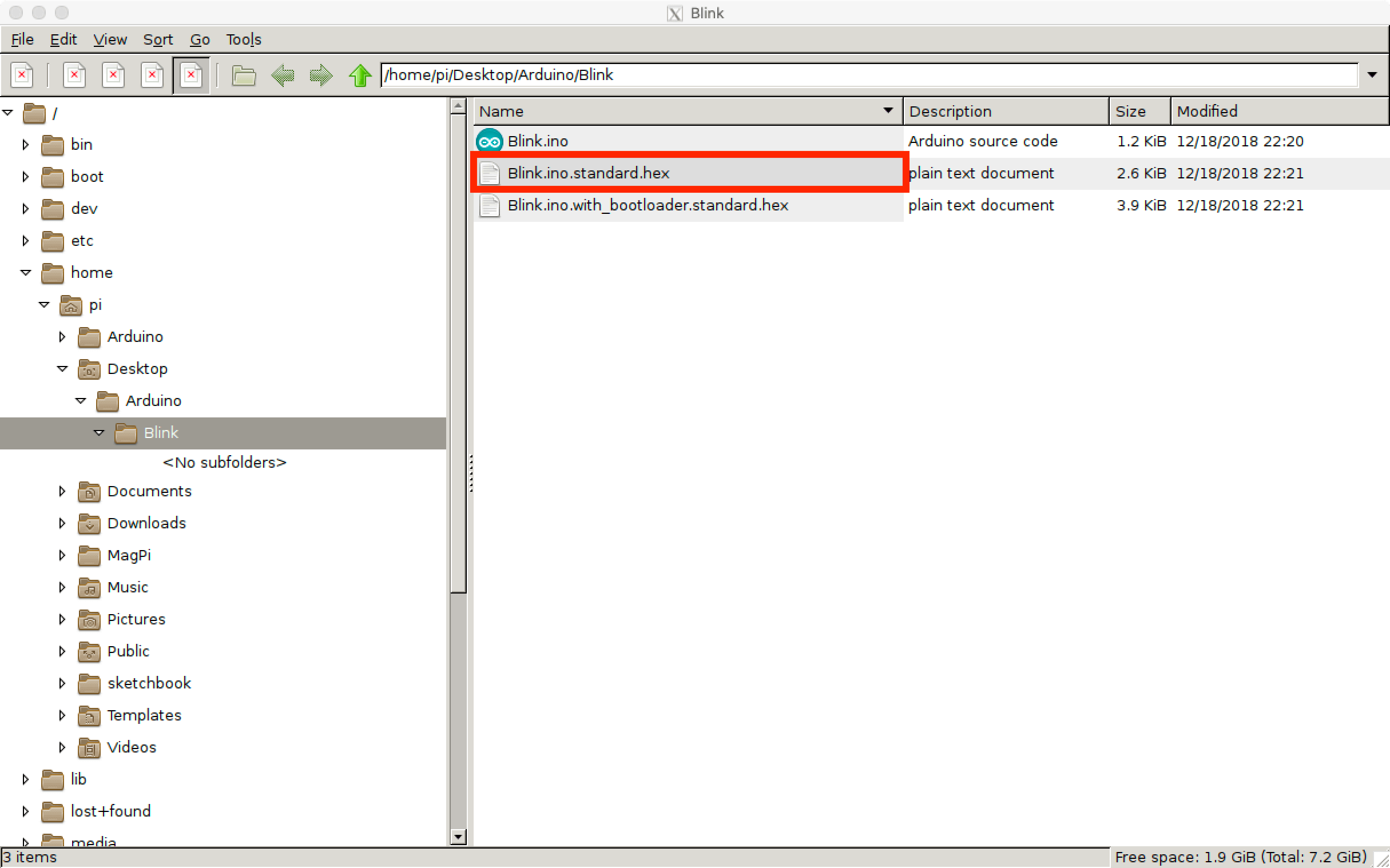 Exported compiled binaries
So that is working fine and with the already included LED’s on the breadboard we can see the results of the Blink sketch in action. To upload the code to the ATmega328p we run the following command
sudo /usr/bin/avrdude -p m328p -c linuxgpio -U flash:w:Blink.ino.standard.hexWhich results in the following output on the console
pi@avrprogrammer:~/Desktop/Arduino/Blink $ sudo /usr/bin/avrdude -p m328p  -c linuxgpio -U flash:w:Blink.ino.standard.hex

avrdude: AVR device initialized and ready to accept instructions

Reading | ################################################## | 100% 0.00s

avrdude: Device signature = 0x1e950f (probably m328p)
avrdude: NOTE: "flash" memory has been specified, an erase cycle will be performed
         To disable this feature, specify the -D option.
avrdude: erasing chip
avrdude: reading input file "Blink.ino.standard.hex"
avrdude: input file Blink.ino.standard.hex auto detected as Intel Hex
avrdude: writing flash (1022 bytes):

Writing | ################################################## | 100% 0.59s

avrdude: 1022 bytes of flash written
avrdude: verifying flash memory against Blink.ino.standard.hex:
avrdude: load data flash data from input file Blink.ino.standard.hex:
avrdude: input file Blink.ino.standard.hex auto detected as Intel Hex
avrdude: input file Blink.ino.standard.hex contains 1022 bytes
avrdude: reading on-chip flash data:

Reading | ################################################## | 100% 0.55s

avrdude: verifying ...
avrdude: 1022 bytes of flash verified

avrdude: safemode: Fuses OK (E:F9, H:DF, L:DF)

avrdude done.  Thank you.
During the upload process the LED labeled ‘PRG’ will be on all the time, the LED labeled ‘ACT’ will be flashing when data is being sent. The LED labeled ‘ACT’ is also the LED that is being addressed by LED_BUILTIN with the code of the Blink sketch.
When the upload is done the LED labeled ‘PRG’ will turn off and the LED labeled ‘ACT’ will keep blinking (1 second on followed by one second off). To create a more interesting blinking pattern I updated the code a bit (and removed the cruft), the LED will now be on for one second followed by two short flashes of .1 second after which the pattern repeats.
bool doBlink = true;
int ledPin = LED_BUILTIN;

void setup() {
  pinMode(ledPin, OUTPUT);
}

void loop() {
  if (doBlink) {
    digitalWrite(ledPin, HIGH);   // turn the LED on
    delay(1000);                  // wait for a second
    digitalWrite(ledPin, LOW);    // turn the LED off
    delay(100);                   // wait for a .1 second
    digitalWrite(ledPin, HIGH);   // turn the LED off
    delay(100);                   // wait for a .1 second
    digitalWrite(ledPin, LOW);    // turn the LED off
    delay(100);                   // wait for a .1 second
    digitalWrite(ledPin, HIGH);   // turn the LED off
    delay(100);                   // wait for a .1 second
    digitalWrite(ledPin, LOW);    // turn the LED off
    delay(1000);                  // wait for a .1 second
  }
}
The programming process and running of the uploaded code in action (and yes I need to get a tripod of some sorts)
Supporting ATtiny micro-controllers
To be able to program the ATtiny micro-controllers we need to add ATtiny boards to Arduino IDE. Open File -> Preferences and in the Additional Boards Manager URLs give this URL https://raw.githubusercontent.com/damellis/attiny/ide-1.6.x-boards-manager/package_damellis_attiny_index.json. After this is done open Tools -> Board -> Board Manager and search for ‘attiny’ and click on the install button.
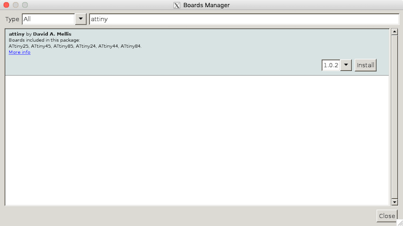 Arduino Boards Manager
After this addition we can build for the following ATtiny micro-controllers:
- ATtiny25 (8 pin)
- ATtiny45 (8 pin)
- ATtiny85 (8 pin)
- ATtiny24 (14 pin)
- ATtiny44 (14 pin)
- ATtiny84 (14 pin)
Depending on which specify clock setting (1Mhz, 8Mhz) you will be using you might need to be update fuse setting (similar to the process for ATmega328p).
Shield version
On AliExpress I ordered a couple of HAT shields for the Raspberry Pi allowing me to ‘built’ a custom programmer. Due to the layout of the board and components required for the programmer I couldn’t fit all of the types I wanted to support (ATtiny45, ATtiny85 and ATmega328P) on the board. The shield pictured below is just for programming the ATmega328P micro-controller (the one needed for the TZXDuino).
Although it looks a bit messy with all of the wires going across the board it works like a charm .
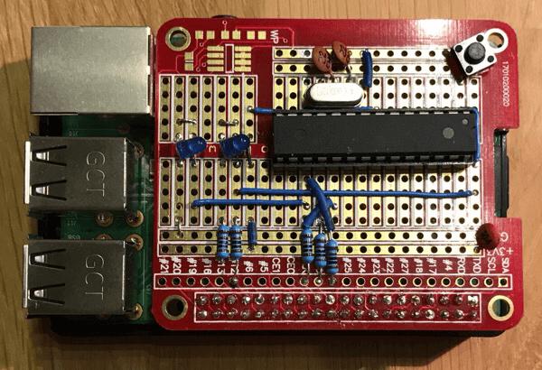 Programmer HAT shield for ATmega328P
Custom PCB version
Based on the schematic created in Autodesk EAGLE I designed a PCB version as well. It has the same size/layout as the HAT shields for the Raspberry Pi. It is based on the B+ HAT Eagle CAD template found on the Raspberry Pi forum. There is also a Raspberry Pi B+ Hat template available on GitHub, but this one is for use with the design program KiCad.
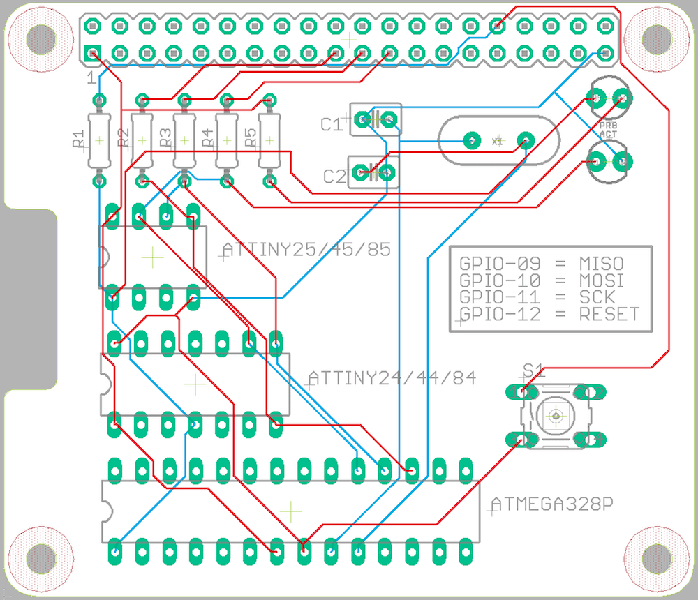 AVR Programmer HAT PCB
With this PCB the following types of micro-controllers can be programmed;
- ATtiny25/45/85 (8 pin) - internal clock only
- ATtiny24/44/84 (14 pin) - internal clock only
- ATmega328P (28 pin)
Since the pin layout of the ATtiny13 is similar to the layout of the ATtiny25/45/85 this PCB could also be use to program an ATtiny13 micro-controller. Just make sure to add support for this micro-controller from the following Boards Manager URL, MicroCore (An optimized Arduino hardware package for ATtiny13) and check for the correct settings (Arduino vs the fuse bits).
Maybe when I will need to flash more micro-controllers I might actually get some PCB’s created, but for now the board for just the ATmega328p is enough. And when that time comes I will also change the layout a bit to make room for ZIF-sockets, because the it was quite hard to extract the ATmega328p from the DIP-socket.